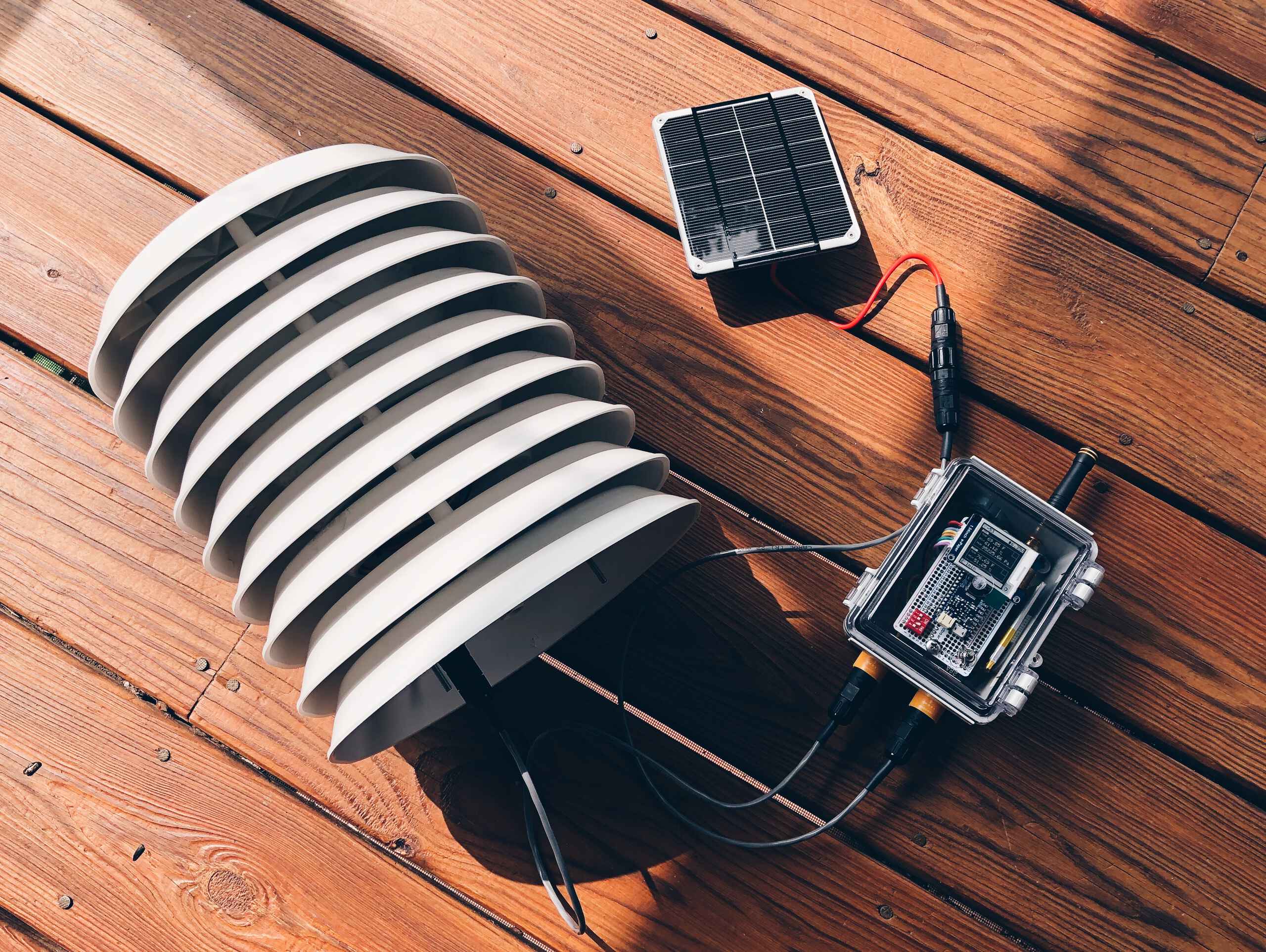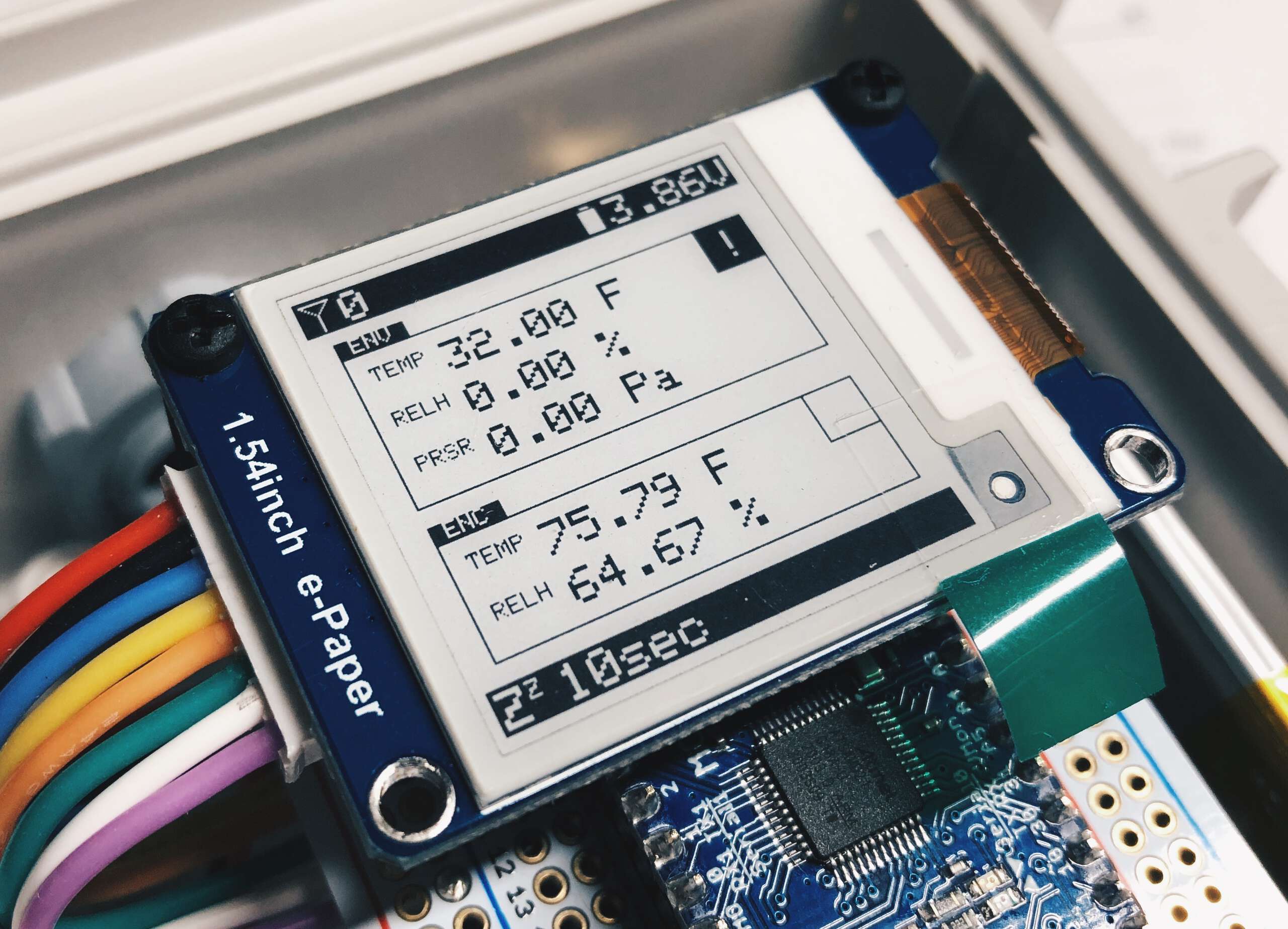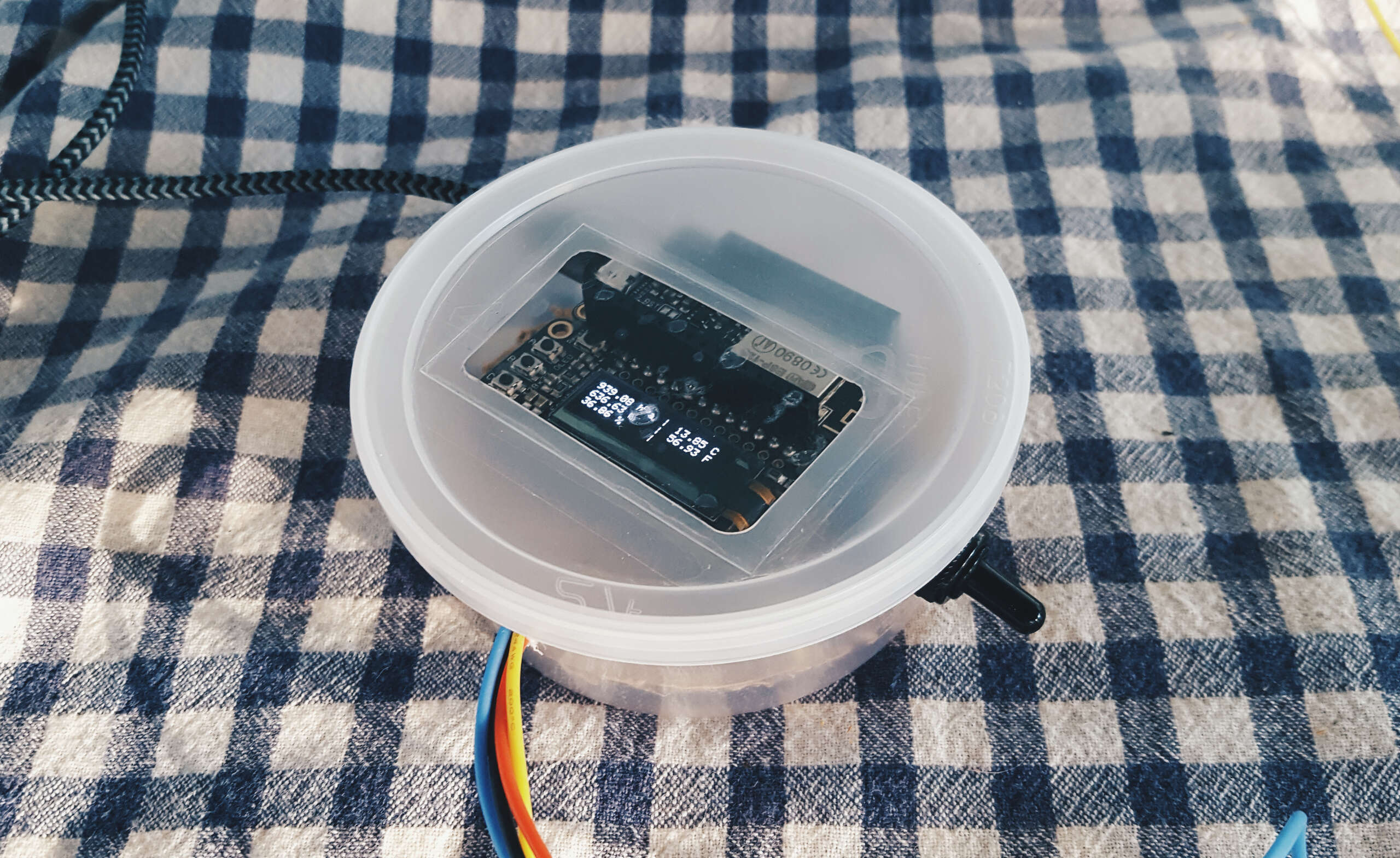
Hardware
Gateway:
Weather Node:
- Moteino M0
- SparkFun Atmospheric Sensor Breakout - BME280
- Lithium Ion Polymer Battery - 3.7v 2500mAh
- Solar Panel - 2W (6V 330mA))
- Solar Charging Board V2 - bq24074
WiFi and RF Network Credentials
You will need to include your own credential header files in the “src” directories of both the gateway and the node.
gateway/src/creds.h
// creds.h for clim-clam gateway

#if defined(ESP8266)
  #include <ESP8266WiFi.h>
#elif defined(ESP32)
  #include <WiFi.h>
#endif

// exactly the same 16 chars/bytes on all nodes
#define RF_ENCRYPTKEY "sixteencharacter"

// wifi ssid and password
// esp8266 can only connect to 2.4Ghz band
#define WIFI_SSID "wifi_ssid"
#define WIFI_PASS "wifi_password"

// address of broker server
#define MQTT_BROKER_SERVER "address.to.broker"
// mqtt client id
#define MQTT_CLIENT_ID "client_id"
node/src/creds.h
// creds.h for clim-clam node

// encrypt key string for packet radio
// exactly the same 16 chars/bytes on all nodes
#define ENCRYPTKEY "sixteencharacter"

// node name
// will be included in payload
// becomes the name of the MQTT topic
#define NODENAME "frank"

// dip switch pins - clim-clam v2.0
#define DIP_DEBUG debug_pin         // logic for debug - serial monitor
#define DIP_SLEEP_1 sleep_pin1      // logic for debug - sleep duration1
#define DIP_SLEEP_2 sleep_pin2      // logic for debug - sleep duration2
Planned Upgrades for V3
Solar Power
Power the node (and potentially other nodes) off a small solar solution with a small battery.
PCB
(This will have to wait for V4)
Design a PCB to be used with the Moteino M0 dev board.
- All connection should be modular - JST connector through hole points for quick access.
- Space allocated for dip switches to set modes.
- Use the
VUSBpin for the power input from the solar supply as it is rated 3.6V-6V, not the USB connector on board the Moteino. This should actually simplify the power management on the PCB over using the connectors. - Local battery can be used on the node, but need to decide if how much it’s worth to have the solar battery charging the batteries of the nodes.
Remove Displays
Node

- Waveshare 1.54in e-paper display (3 color - black + white)
- The display is fun, but it’s also unnecessary bloat for the node and doesn’t provide any additional debug info that isn’t already obvious.
- Draws the most current (only during screen update).
Gateway
- FeatherWing OLED - 128x32 OLED
- The gateway just needs to pass packets on to the broker server. In practice, we shouldn’t even be looking at the device.
Code
- Write better code.
- Give more feedback about the state of the node.
- Better grasp of the networking - channels, broadcasting and node IDs.
- Get the gateway working on the ESP32 - not urgent, but would free up some more functionality.
Hardware Info
More weather proof hardware.
- McMaster Carr Mil Spec connectors: LINK
JST for PCB.
- JST spec: LINK
Notes
Battery
Replaced a fully charged batter on Feb. 5 2019. Sample rate: 5 min. Battery samples: 100.
Upping the battery voltage sample rate from 10 to 100, still gives us some-what inconsistent readings, so it’s probably not worth the waking cycles.
Replaced full battery on APR. 6 2019 11:15 AM. Died JUN. 0 2019 2:00 PM (roughly and was fluctuating sample rates…).
Power
(I don’t have the equipment to measure such low current so this is probably all bs and should be disregarded.)
This is with sleeping the controller, sensor and transmitter.
| Period | Current Draw | Duration |
|---|---|---|
| during code execution | ~ 15mA | 1.2 sec |
| during sleep | ~ 610uA | 15 min |
With a 1200mAh battery will potentially run for 78 days.
Dev DIP Switches
| Switch Position | Operation |
|---|---|
| U,D,D,D | wait for active serial monitor then run |
| D,D,D,D | 15 minute sample rate |
| D,U,D,D | 5 minute sample rate |
| D,D,U,D | 1 minute sample rate |
| D,U,U,D | 10 second sample rate |
Wrench/Socket Sizes (for my sanity)
| Part | Size |
|---|---|
| Antenna | 5/16" |
| Aviation Connector | 5/8" |
| Momentary reset switch | 10mm |
| Toggle switch | 10mm |
| Barrel jack | 7/16" |
To do
- more accurate battery monitoring
parse packet message and display relevant data- reduce power consumption
rework expected TX counter- Better yet, replace “countdown” with a log
debug switch (if low wait for serial monitor to run/set shorter sleep period)- LWT for failed connections
- Adjust for multiple nodes
- Sparkfun lib has trouble detecting failed bme init - when it fails it just hangs (no way to send further output…need to figure out work around)
To remember
- when programming/flashing the hex files to the m0, put it into bootloader mode (causes my machine to shutdown unexpectedly…)
rtc.standbyMode()will put the chip to sleep - I was putting it in standby mode it a second time manually. this is likely why i had to half to alarm for the sleep period.
Version History
V0.1
Proof of concept. Lowest bar to entry.

- Data sent directly over WIFI to MQTT broker (no RF).
- Had to be powered from wall socket (no battery).
- Device was on a simple delay between sample rates (no sleep mode).
V0.2
- Protoboard.
- Dip switches.
- Sleep mode.
V1
- NEMA rated enclosure.
V2
- Move to Moteino M0 board.
V3.1
- 6V 2W Solar Panel.
- Solar charging board for lithium ion/polymer batteries (v2).
- Upgraded IP67 power and sensor data connectors.
- Upgraded outdoor 916MHz 1/4 wave monopole whip antenna.
- Additional rubber o-ring washers for weatherproofing the RP-SMA connection.
V3.2
- Updated solar charging board to the bq24074 version (previous board).